ER-2013-A Floor Controller
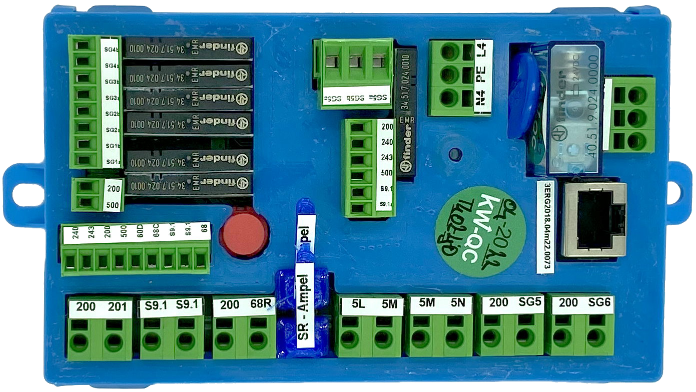
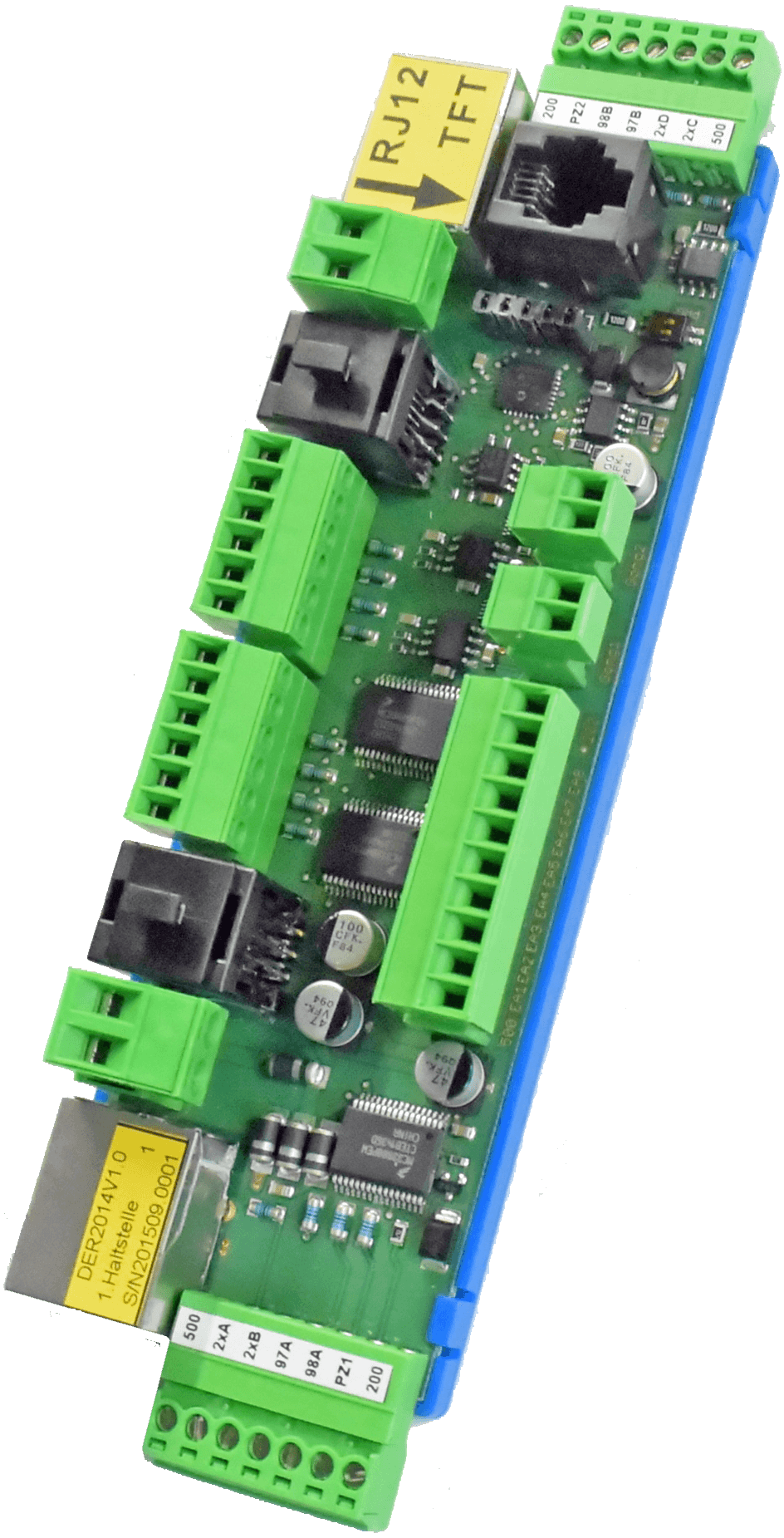
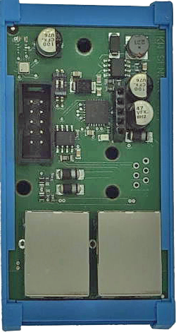
The ER-2013-A floor controller offers 16 inputs and outputs, of which 6 inputs and outputs are freely assignable, two piezo buzzer outputs for call acknowledgment, 8 outputs for controlling floor indicators, 4 outputs for floor bell speakers, as well as the possibility to connect two bus matrix displays and 1x RJ-12 for TFT graphic displays.
All necessary call inputs, as well as arrow outputs, even for selective door control, are available.
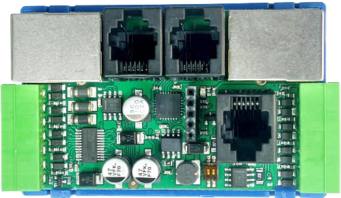
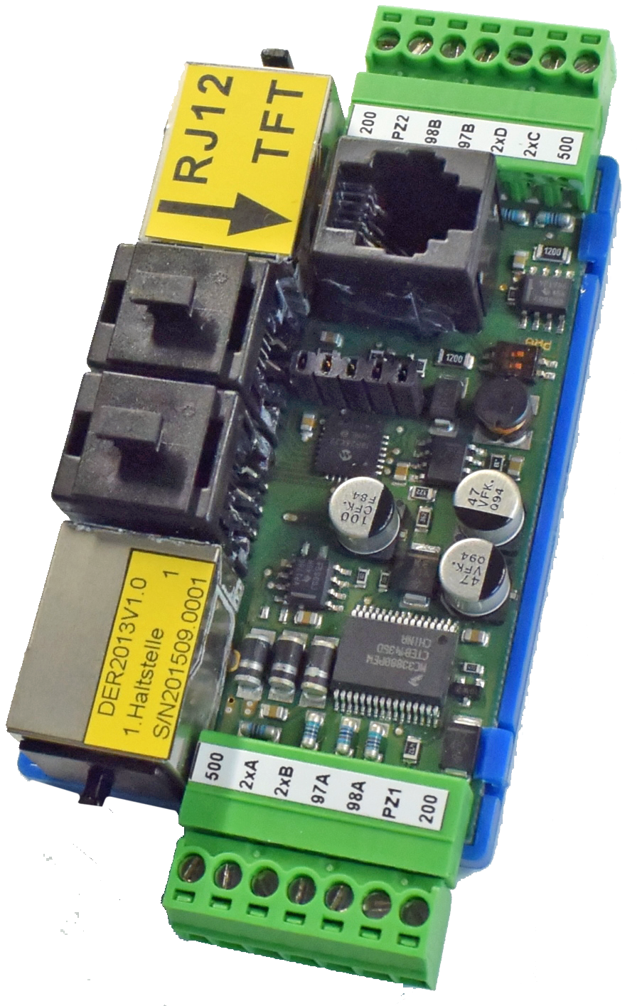
The floor controller is mounted in the shaft cable channel. The connection cable for the bus is the blue RJ-45 cable and a power cable. The lower 7-pin connector with the call lines 2xA & 2xB is intended for Door side 1, while the upper connector with 2xC & 2xD is for Door side 2. The matrix displays are connected using the RJ-12 cable inserted into the two black sockets. The yellow marked RJ-12 socket is for high-quality TFT graphic displays with KW bus connection.
Difference to the ER-2013:
New software to control the output driver ICs of the type TLE75080. The software automatically recognizes which floor controller it is. Usable for all variants!
External protection diodes are no longer required!
Transil protection diodes are already built-in.
No residual voltage when the output is set to "0".
Control of the LED matrix display has been optimized.
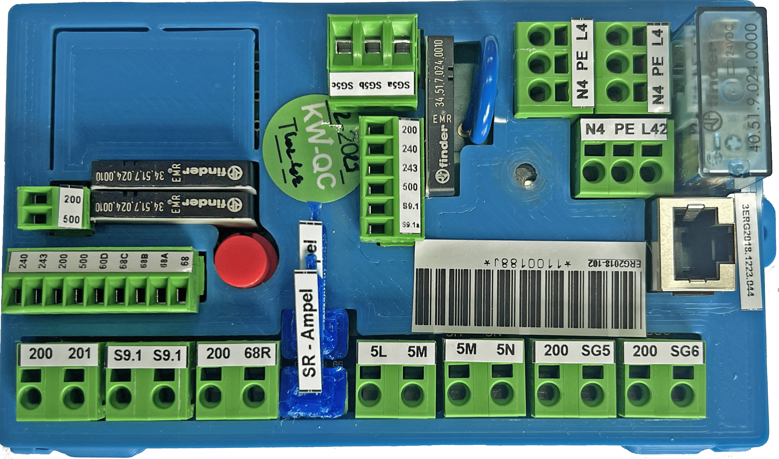
ER-2013 Floor Controller
The floor controller ER-2013 offers 8 inputs and outputs. All necessary call inputs, as well as arrow outputs, even for selective door control, are available.The installation of the floor controller is done in the shaft cable channel. The connection cable for the bus is the blue RJ-45 cable. There is the possibility to connect two bus matrix displays and 1x RJ-12 for TFT graphic displays.All necessary call inputs, as well as arrow outputs, even for selective door control, are available.The lower 7-pin connector with the call lines 2xA & 2xB is intended for door side 1, the upper connector with 2xC & 2xD is for door side 2. The matrix displays are plugged into the two black sockets with the RJ-12 cable.The standalone RJ-12 socket is for high-quality TFT graphic displays with KW bus connection.
ER-2014-A Floor Controller
The floor controller ER-2014-A provides 16 inputs and outputs, of which 6 are freely configurable, two piezo buzzer outputs for call acknowledgment, 8 outputs for controlling floor indicators, 4 outputs for floor gong speakers, as well as the connection option for two bus matrix displays and 1x RJ-12 for TFT graphic displays.
All necessary call inputs, as well as arrow outputs, even for selective door control, are available.
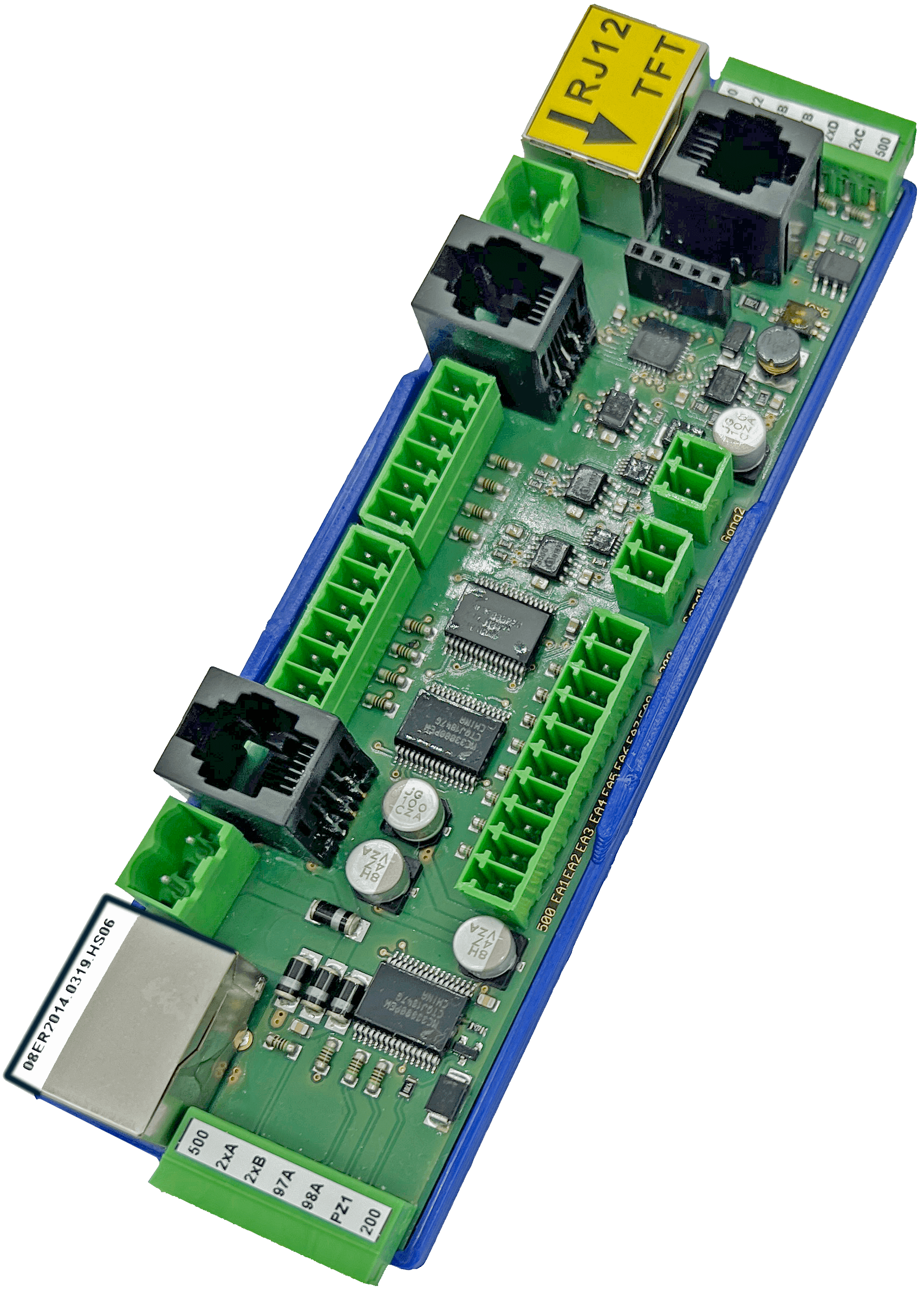
The floor controller is mounted in the shaft cable channel. The blue RJ-45 cable and a power cable are used for the bus connection. The lower 7-pin connector with the call lines 2xA & 2xB is intended for door side 1, the upper connector with 2xC & 2xD for door side 2.
The matrix displays are connected using the RJ-12 cable in the two black sockets.
The yellow-marked RJ-12 socket is for high-quality TFT graphic displays with KW bus connection.
New software to control the output driver ICs of type TLE75080. The software automatically detects which floor controller it is. Usable for all variants!External protection diodes are no longer required! Transil protection diodes are already installed. No residual voltage when the output is set to "0".
Control of the LED matrix display has been optimized.
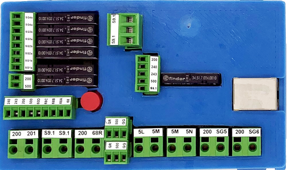
ER-2014 Floor Controller
The ER-2014 floor controller offers 16 inputs and outputs, of which 6 are freely assignable, two piezo buzzer outputs for call acknowledgment, 8 outputs for controlling display panels, 4 outputs for floor gong speakers, as well as the possibility to connect two bus matrix displays and 1x RJ-12 for TFT graphic displays. All necessary call inputs, as well as arrow outputs, even for selective door control, are available. The installation of the floor controller takes place in the shaft cable channel. The blue RJ-45 cable and a power cable serve as the bus connection. The lower 7-pin connector with the call lines 2xA & 2xB is intended for door side 1, the upper connector with 2xC & 2xD for door side 2. The matrix displays are connected to the two black sockets using the RJ-12 cable. The yellow-marked RJ-12 socket is for high-quality TFT graphic displays with KW bus connection.

