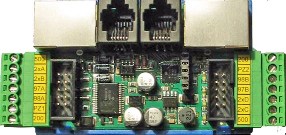
ER-2007 Floor controller
The floor controller ER-2007 provides 8 inputs and outputs. All necessary call inputs, as well as arrow outputs, even for selective door controls, are available.
The installation of the floor controller is carried out in the shaft cable duct. The blue RJ-45 cable is used as the connection cable for the bus. There is the possibility to connect two bus matrix displays.
All necessary call inputs, as well as arrow outputs, even for selective door controls, are available.
The lower 7-pin connector with call lines 2xA & 2xB is intended for door side 1, while the upper connector with 2xC & 2xD is for door side 2.
The matrix displays are connected using the RJ-12 cable into the two black sockets.
| Name of the assembly group: | ER-2007 |
|---|---|
| Use function: | The ER-2007 floor controller provides 8 inputs and outputs. All necessary call inputs, as well as arrow outputs, even for selective door controls, are available. |
| Obsolete component: | ER-2006 |
| Time of use: | From 2007-07 to 2009 |
| Relay elements: | None |
| Dimensions (with shell): | (length x width x height) 130 mm x 46 mm x 30 mm |
| Weight: | Approx. 200 gram |
| Power supply: | Terminals 200 - 24V DC
Terminals 500 - 0V GND |
| Switching cycles: | None |
| Protection level: | IP 43 / Pollution degree II |
| Place of installation: | In the elevator shaft - cable channel |
| Ambient temperature: | 0 to +45 °C |
| KW-Number: | 1100153 (Software of the ER-2007 on the hardware of the ER-2013-A) |

